Eine deutsche Version dieses Dokuments ist vorhanden.
Remark: The following document uses the Windows font Symbol for displaying greek characters. If your browser doesn't support displaying these characters, you will see the corresponding latin characters instead (D=Delta, e=Epsilon, s=Sigma, p=Pi)
I am always happy to receive feedback (e.g. new application examples)
on this program. I'm also thankful for reports of errors within the program
or this document (especially concerning the language. Don't hesitate to
tell me the mistakes in my English. I am a perfectionist and always want to learn.).
Please send feedback to Matthias Benkmann
(m.s.b (a) gmx.net)
Of course you are encouraged to distribute this program. Its free software
(Freeware).
This HTML document is the official manual for the Molecular Dynamics Simulator. With the download of the program also comes an unformatted ASCII copy of this page.
We all do have an intuitive idea of terms like "warm" or "cold".
We also know what a liquid is like. But if you ask for a more precise explanation
of what these terms mean on the microscopic level, many people won't have
an answer. On the other hand there are phenomenons that you can illustrate
quit well, like for example the planets circling around the sun. You just
have to put a globe in the middle of the room and then walk around it with
a marble in your hand. However, you will have a hard time demonstrating
Kepler's Laws this way.
Sometimes it is impossible with the means available in school, to show
the students experiments to illustrate a certain topic. The means of the
teacher often don't exceed static pictures. The explanation of the states of
matter with the model of balls packed dense or less dense,
is a good example for this. And even if a film is available, it has the
great disadvantage of missing interactivity.
The computer can help the teacher with all these problems, which is why it will surely become one of the most important educational tools of the future. Computer programs are, of course, unable to replace the real experiment, but they offer the possibility of simulating things that are otherwise hard or impossible to show in class. Additionally they offer the opportunity of actively manipulating what does happen on screen. Even absolute impossibilities, like reversed gravity or time may be tried out on the computer.
The program "Molecular Dynamics Simulator" (MDS) was developed for the simulation of the processes in a multi-particle system. Of course it is possible and, depending on the context, sometimes necessary to work with just a few particles. In designing the program it was a goal to combine an appealing and colourful look with maximum usability, but without making compromises in the physics behind it.
The program needs an IBM-compatible PC. A CPU of the type i80386 (or compatible) must at least be present. An i80387 compatible co-processor is also required. A color monitor and a graphics adaptor that is 100% compatible to the IBM Video Graphics Array (VGA) are necessary, too. The program will run under DOS Version 3.0 or above and in full-screen DOS-sessions under all operating systems which can provide 502000 Bytes of conventional memory and allow that the program accesses all registers of the graphics adaptor and the PIT (Programmable Interval Timer) directly. Take note of the fact that, depending on operating system and graphics driver, the 360x480 "tweaked" mode can possibly not be restored after a task switch. Though extremely improbable and up to date not observed, damage to the monitor due to wrong synchronisation, is not impossible, especially on older models. For that reason it should be avoided to task-switch to another application, while working with the Molecular Dynamics Simulator (MDS). Additionally the screen-saver should be deactivated for MDS. Know that in case of problems you can always terminate the Molecular Dynamics Simulator (MDS) immediately by pressing ALT-X (two times if the simulation is currently running).
THE PROGRAMMER WANTS YOU TO TAKE NOTICE OF THE FACT THAT THIS PROBLEM IS DUE TO A BUG IN THE RESPECTIVE OPERATING SYSTEM SOFTWARE AND NOT IN MDS. IF YOU HEED THE ABOVE ADVICE OR EXECUTE THE PROGRAM UNDER PLAIN DOS, NO DAMAGE HAS TO BE FEARED.
EVEN IN THE CASE OF ERRORS FOR WHICH THE PROGRAMMER IS RESPONSIBLE,
THE PROGRAMMER WILL NOT BE LIABLE FOR ANY DAMAGE IN DIRECT OR INDIRECT
CONNECTION TO THIS SOFTWARE. BEFORE EXECUTING THE PROGRAM, THE USER MUST
MAKE SURE THAT THE ABOVE IS LEGAL IN THE AREA WHOSE JURISDICTION APPLIES
TO THE USER. IF THIS IS NOT THE CASE THEN THE PROGRAMMER DOES NOT ALLOW
ANY EXECUTION OF THE SOFTWARE.
(TAKE NOTE OF THE COMPLETE DISCLAIMER IN THE FILE README.TXT BEFORE EXECUTING
THIS PROGRAM.)
The program tests at the beginning, whether the system meets the minimum requirements and terminates with an error message if not. However, it is possible that your graphics adaptor is not 100% IBM VGA compatible but passes the test anyway. In this case the graphic output will appear garbled but you can still terminate the program by pressing ALT-X.
The movement of the particles is simulated step by step. For every step, the forces caused by the potentials are summed for every particle. From these forces the new locations and velocities for the particles are computed using the formulas F=ma, v=v0+a*Dt, x=x0+v*Dt. The time step Dt on which the calculation is based may be chosen by the user.
The values in the program are based on the respective SI-units.
The angles between the velocity components are measured in degrees, which
is explicitly marked by [°] in the Properties
menu.
+INF and -INF (INFinite) in the
displays mean that for the current set-up of particles the value displayed
is either out of the display's range, or that a division by 0 has occurred.
The latter usually happens if the user has accidentally placed two particles
in exactly the same location which means that their distance is 0. While
computing the potential this creates a division by 0.
+NAN and -NAN (Not A Number) usually appear if (again due
to an erroneous set-up) an undefined computational operation occurs which
cannot be answered sensibly with an infinity (e.g. square root of a negative
value).
However, the program is so good-natured that it punishes neither infinities
nor NANs with an error message or even a crash. This means there is nothing
to stop you from unrestrained playing with the program's options.
The potentials supported for the interactions between particles are listed in the table below. There is also the possibility of having the particles act like hard balls on collision.
| Potential | Epot ij | Fij | Epot=0 for | F=0 for | Application example |
| Lennard Jones | -4es6(r6-s6)/r12 | 24es6(r6-2s6)/r13 | |r|=s | |r|=s*21/6 | van-der-Waals-forces in inert gases |
| Quadratic | -e+36e*(r-r0)2/r02 | 72e*(r-r0)/r02 | r=7r0/6 or r=5r0/6 | r=r0 | Pseudo-gas(atoms linked with Hook-springs) Approximation for Lennard Jones |
| Gravitation | -G*mi*mj/r | G*mi*mj/r2 | _____ | ______ | Kepler's Laws |
| Coulomb | qi*qj/(4pe0r) | -qi*qj/(4pe0r2) | _____ | ______ | Bohr's atomic model |
Epot ij is the potential energy of the
particle pair ij. Negative values mean that the two particles attract each
other.
Fij is the force that the particles i and
j exert upon each other. Positive values mean attraction.
r0 is the distance between two particles
for which Fij=0 is true.
e,s are constants depending on the kind of particles
concerned.
G is the gravitational constant.
qi,qj is
the electric charge of the particle i or j respectively.
e0 is the electric
field constant.
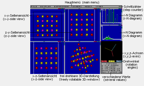
This picture shows all windows of the program. All but the main menu can be turned on and off independently.
Main menu: Here you can find the sub-menus
"File","Display","Experiment"
and "Others". The button for switching
between view mode and edit mode and the button
to start/stop the simulation are also located here. Left-click opens
the menus or activates the buttons respectively.
Step counter: Counts the steps calculated
for the current experiment
r-N-Diagram: For every distance r the
diagram shows how many neighbouring particles you will find on the average
in this distance from a particle. The momentary values are drawn as green
lines while the mean values are plotted as white dots.
The unit of the horizontal axis is 360/scale
meters rounded down to the next power of 10 (scale
is the value that was entered in the menu Display/Diagrams
for the menu item scale.). The unit
of the vertical axis is 1.
The first yellow number reflects the average number of next
neighbours (particles whose distance is less than the value entered for
Display/Diagrams/next sum r)
of a particle. The second yellow number shows the average distance of a
next neighbour. The red line marks the distance Display/Diagrams/next
sum r.
v-N-Diagram: For every velocity v the
diagram contains the number of particles which have this velocity. The
momentary values are drawn as green lines while the mean values are plotted
as white dots.
The unit of the horizontal axis is 360/scale
meters per second rounded down to the next power of 10 (scale
is the value that was entered in the menu Display/Diagrams
for the menu item scale.). The unit
of the vertical axis is 1.
Several values: This window displays
the values for pressure (p), temperature (T), volume (V) and the average
kinetic energy per particle (Ek), as well as the average potential energy
per particle (Ep). Via the button current/mean you can toggle between
current and mean values. For Ek and T you may enter new values that become
effective immediately. For the volume you may
enter a target volume which the simulation will try to reach by moving
the walls in steps of ½Ds.
(½Ds can be altered
via Experiment/Parameters/ ½Ds).
Attention: Entering a target volume will deactivate pressure
adaption.
freely rotatable 3D-window: This window
displays the ensemble of particles rotated around the x-,y- and z-axis
as a perspective drawing. The rotation order is z-rotation, x-rotation,
y-rotation. Left-click on a particle in this window opens the properties
menu where the properties of the clicked particle are displayed and
may be modified.
x,y,z-axes: This window shows the x-,y-
and z-axis, rotated according to the current rotation angles (parallel
projection). Left-click into this window of the Molecular Dynamics Simulator
and hold the mouse button pressed. This
enables you to rotate the axes by moving the mouse around. The current
rotation angles are displayed at the bottom
of the window. Left-click on a digit increases it with carry, right-click
decreases it. If you hold the mouse button pressed, increasing/decreasing
will be done continually after a short delay.
Side view windows: These windows
show the respective sides of the ensemble (parallel projection).
The black rectangles reflect the boundaries of the
volume where the particles are trapped. Display of these lines can be toggled
on and off via Display/Smiley Windows/draw borders.
The white lines which can be moved holding the
left mouse button pressed, mark the current view levels. Only particles
located between the white lines will be drawn. All the others are (in the
3D-window, too) invisible.
Via Display/Smiley windows/Reset view levels
you can set all view levels at the same time back to their maximum
values.
Left-click on one of the particles in a side view window or the
3D-window to open the window with the particle
properties.
In the freely rotatable 3D-window and in the side view windows
you can move the window contents with the arrow keys. With the + and -
buttons at the top of the window it is possible to zoom the displayed section
nearer or farther away. The arrows at the borders of the particle- and
diagram-windows allow changing the window size
by left-clicking and dragging them with the button pressed.
The button marked "Z" in the top right corner
of the window zooms the respective window to maximum size. Clicking it
again restores the previous layout.
Right-clicking into a window and dragging the mouse into another window
with the button pressed, will swap the two windows.
MAIN MENU
-->edit/view switches to the respective
mode. (see "The edit mode")
start starts the simulation unless the step
counter has already reached Experiment/Parameters/Max. steps.
FILE
Load opens the file selection window for loading
an .MDS file.
Save opens the file selection window for saving
an .MDS file.
Grab PCX opens the file selection window for
saving a screenshot as .PCX file.
Quit terminates the program.
DISPLAY
invisibles switches displaying of particles
marked as invisible on or off.
slicing see Display/Smiley Windows/Slicing.
D-Scheme changes the window layout.
Step counter turns the step counter display
on or off.
DIAGRAMS
r-distribution turns displaying of the
r-N-diagram on or off.
after steps reflects after how
many steps the diagram contents will be recalculated and added to the mean
values.
scale is a factor for transforming
the floating point values into integers before plotting them in the diagram.
Scale is indirectly proportional to the unit of
the horizontal axis.
offset determines how much the diagram will
be shifted left.
devalue after determines after how many
diagram refreshes the contents of the buffer for the diagram's mean values
will be divided by 2. This function makes sure that, even after a great
amount of steps, the diagram's mean values will still react to changes.
If you enter 0 here then the function will be disabled.
next sum r reflects the maximum distance
a particle may have while still being counted as a next neighbour.
v-distribution turns displaying of
the v-N-diagram on or off.
Reset mean values restarts
calculation of the mean values for the diagrams.
MISCELLANEOUS
Miscellaneous turns the display of p,V,T,Ek
and Ep on or off.
after steps reflects after how many
steps the values will be recalculated.
mean buf size determines how many of
the recalculations, that are done every after
steps steps, will be taken for the calculation of the mean values.
If you enter 0 here, all values calculated after the last reset of the
mean values will be taken into the mean value calculation.
Reset mean values restarts the
calculation of the mean values.
SMILEY WINDOWS
Rotatable 3D turns displaying of the freely
rotatable 3D-window on or off.
x,y,z axes turns displaying of the x,y,z-axes
window on or off.
slice start determines how far away from
the viewpoint in the 3D-window the displayed
slice is located (measured in pixels).
thickness determines how thick the slice
displayed in the 3D-window is (measured in
pixels).
slicing causes particles outside of
the slice described by slice start
and thickness not to be displayed in the
3D-window. This is very useful for instance
if you want to look at the hexagonal basic structure of an FCC-lattice.
You just define a slice by setting slice start
and thickness. Then you rotate the 3D-window
till the structure is visible.
x-y side view, x-z side view, z-y side view
turns displaying of the respective
window on or off.
after steps reflects after
how many steps the 3D-window and the side
view windows will be refreshed.
slime tracks makes the particles leave
a trace as they move.
draw borders turns displaying of the
volume boundaries on or off.
smiley size reflects the size of the particles
in the displays if r-scaling is deactivated.
z-scaling activates scaling of the particle
sizes depending on the distance to the viewer in the side
views, too. (in the 3D-window z-scaling
is always used).
r-scaling turns scaling of the particle
sizes depending on the particle radius on or off.
Reset view levels sets the view
levels back to the respective maximum values.
v-vectors turns displaying of the velocity
vectors on or off.
scale reflects the factor with which
the lengths of the velocity vectors are multiplied prior to being drawn.
EXPERIMENT
Description shows the description of the
current experiment and lets you change it.
Reset step counter sets the step counter
to 0 and thus defines the beginning of a new experiment, i.e. Restart experiment
will now restore the set-up at the time of the reset.
Restart experiment restores the initial
set-up of the current experiment. A new experiment is defined by Reset
step counter, load (with properties
activated) or Experiment/Build lattice/build lattice.
POTENTIAL TYPE
Lennard Jones, Quadratic, Gravity, Coulomb selects the respective potential
for the molecular dynamics simulation. You can activate more than one potential at the same
time.
s,e,e0,r0,G
are the constants specific to a potential. For details on the different
potentials see above at "Supported
potentials".
cutoff determines the distance between two
particles above which the interactions of the respective potential will
be ignored. A cutoff may be used to save computation time. Attention: If
the quadratic potential shall be
used as approximation for the Lennard
Jones potential, you have to set cutoff<=7r0/6.
PARAMETERS
Dt is the time step
which is the basis of all computations.
collision check makes the particles
behave like hard billiard-balls if they collide. Attention: Collisions
are calculated based on the particle radius entered in the properties
menu, not based on the radius in the display.
downwards gravity turns a constant
acceleration in y-direction for all particles on or off.
g is the acceleration for downwards
gravity.
p turns volume adaption to achieve a constant pressure
on or off.
Attention: If you select adapted pressure, a target volume entered in the
several values window will become inactive.
Just the same is true the other way around. A target volume deactivates
pressure adaption.
target reflects the pressure that
the volume adaption tries to achieve.
V-adapt Dsteps
determines how many steps will pass between the volume
adaptions.
½ Ds
reflects the distance that each of the 6 walls will be moved at each volume
adaption.
c is the temperature, that the temperature
adaption will try to reach within the next few steps.
f is the factor (if exponential heating/cooling
is chosen) with which c will be multiplied after
each temperature adaption.
DT is the value
that will be added to c after each temperature
adaption if linear heating/cooling is chosen.
Dsteps determines
how many steps will pass between the temperature
adaptions.
Max. steps reflects the number of steps
after which to stop the simulation. Attention: If the step counter has
reached this value then you can not start the simulation again before you
do either set the step counter to 0 (Experiment/Reset
step counter or Experiment/Restart experiment),
or increase Max. steps.
TEMPERATURE ADAPTION FUNCTIONS
free turns off temperature adaption.
T=c, c=const. configures temperature adaption
to try to hold T constant at c.
T=c, c=c+ DT
configures temperature adaption to increase the target temperature c
in steps of DT. This corresponds to a linear
heating/cooling.
T=c, c=c*f configures
temperature adaption to multiply the target temperature c
with the factor f after each adaption. This corresponds
to an exponential heating/cooling.
BOUNDARIES
The blue window shows the front and the right side of the virtual box that
contains the particles, drawn as black rectangles. The green rectangles
mark the volume currently occupied by particles. You can move the ensemble
within the box by dragging it with the left mouse button pressed. If this
leads to particles being moved out of the box, then a red line appears
on the respective side, to warn you that on acknowledging the move via
Set new boundaries some particles
will be deleted.
Attention: Due to a little bit of tolerance, it is possible that even though
a red line is drawn, no particles will be deleted.
Periodic boundary turns calculation
with periodic boundaries on or off.
Changing this setting becomes active the next time you start the simulation.
You do not need to click on Set new boundaries
first.
x,y,z reflects the current length of
the respective side of the box. Although any changes here will be displayed
at once in the blue window, you have to click on Set
new boundaries before the changes will become active. Before doing
this no particles out of the box will be removed.
Set new boundaries causes the changes
of the side lengths and any moving done in the blue window to become active.
Particles out of the box will be deleted.
The number of particles that are simulated in the Molecular Dynamics
Simulator (MDS) is very small compared
to that in a real environment. So if you simulate a solid with the
Molecular Dynamics Simulator (MDS), then
the portion of the body taken by particles located at the sides is very
high. These are particles that have fewer next
neighbours than those in the center of the body. For that reason they
are bound less to their position which may lead to their detaching from
the body. Additionally you do not get the correct number of next neighbours
which is characteristic for every type of lattice.
With the help of the "computational trick" periodic boundaries
it is possible to overcome these difficulties. 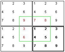 The trick is to assume that, connected to the box actually being simulated
(bold rectangle), there are additional identical boxes. For the computation
of the forces that affect particle 1 you do now take the neighbouring
particles from a virtual box (green rectangle)
where particle 1 is exactly in the center. Thus particle 1
from the example "sees" only the particles 2,4 and 5
at their real locations. The particles 3,6,7,8 and 9 appear
as virtual particles 3,6,7,8
and 9. It is quite obvious that a seamless
connection of the boxes can only be achieved if the volume and the particle
set-up are, as in this picture, chosen correctly. If Experiment/Boundaries/periodic
boundary is tagged, then Experiment/Build lattice/build
lattice takes precautions for a seamless periodic continuation
of the chosen lattice type. However, if during simulation the lattice type
changes, you have to manually take care that the volume is appropriate
for a periodic continuation of the respective lattice type (e.g. enter
a target volume in the several
values window).
The trick is to assume that, connected to the box actually being simulated
(bold rectangle), there are additional identical boxes. For the computation
of the forces that affect particle 1 you do now take the neighbouring
particles from a virtual box (green rectangle)
where particle 1 is exactly in the center. Thus particle 1
from the example "sees" only the particles 2,4 and 5
at their real locations. The particles 3,6,7,8 and 9 appear
as virtual particles 3,6,7,8
and 9. It is quite obvious that a seamless
connection of the boxes can only be achieved if the volume and the particle
set-up are, as in this picture, chosen correctly. If Experiment/Boundaries/periodic
boundary is tagged, then Experiment/Build lattice/build
lattice takes precautions for a seamless periodic continuation
of the chosen lattice type. However, if during simulation the lattice type
changes, you have to manually take care that the volume is appropriate
for a periodic continuation of the respective lattice type (e.g. enter
a target volume in the several
values window).
In addition to the computational trick explained above, having periodic boundaries
activated causes particles that reach a side of the box to be, instead of
being reflected as usual,
put back into the box at the opposite side.
BUILD LATTICE
x,y,z-direction cell no. reflects the length
of the respecive side of the lattice to be built, in unit cells.
Unit cell side determines the length of
the sides of the cubic unit cell.
Velocity/p. determines the velocity assigned
to every particle when the lattice is built. The directions of the velocities
will be distributed in way that leaves the total momentum 0. An angular
momentum may remain, though. If the number of particles that have to be
created is odd then one particle gets velocity 0.
Lattice type reflects the kind of lattice
to build. You may choose from simple cubic, face-centered
cubic and body-centered cubic.
Lattice error determines whether particle
no. 0 will get a 1 percent deviation from the correct starting position
to avoid unrealistic symmetry effects.
Build lattice builds up the lattice
and thus defines the beginning of a new experiment (see Experiment/Restart
experiment). If Experiment/Boundaries/periodic
boundary is activated, then the lattice will be built in a way
that enables a seemless periodic continuation.
OTHERS
Watchdogs determines whether the guard dogs
run free. If this is the case then particles outside of the box will be
bitten to death without mercy and the message "Woof!" will be
displayed. If particles exceed the maximum velocity
entered then you will be notified by "Arf!". In this case the
particles will be left alive.
Attention: While exceeding the maximum velocity is
not so unusual, leaving the box is something that a particle cannot usually
do as particles are reflected at the walls (Experiment/Boundaries/periodic
boundary deactivated) or will be put back into the box at the opposite
side (periodic boundary activated).
This means that if a particle really leaves the box this is a sign for
a set-up with forces or velocities that are too extreme, or that the time
step is too great for the forces/velocities. (see also Remarks
on the displays)
vmax is the maximum velocity tolerated by the
watchdogs.
Current Smileys reflects the total
number of particles currently within the ensemble.
Recalculate diagrams/misc. recalculates
the contents of the diagrams and p,T,Ek,Ep.
This function is useful if you have changed the set-up and want to check
the potential energy, to see whether you have created a constellation
with too extreme forces.
THE PROPERTIES MENU
The properties menu is opened by left-clicking a particle. The following
properties will be displayed and may be modified:
color, group status, invisibility
status, mass(m), charge(q), radius(r), x,y and z-coordinate, absolute
velocity(v), angle between x-component(vx) and y-component(vy) of the velocity
vector, angle between vx and vz, angle between vz and vy.
Via the group status it is possible
to define a group of particles. This makes sense if you want to modify
many particles at a time (see example).
Thus you can (via !DELETE GROUP!) delete
all particles of the group (i.e. all with grouped: yes) at the same
time, or you may (via Group....=Smiley....)
assign the property .... of the currently displayed particle to
all grouped particles with just one click (see example).
Invert group inverts the assignment of
particles to the group, i.e. all particles which have belonged to the group
will not be in the group, and all particles not in the group will make
up the new group (see example).
Ungroup all sets all particles to grouped:
no. In conjunction with Invert group
it is thus very easy to modify the whole ensemble (see example).
Example: All particles shall be assigned a mass
of 1kg. First you set the currently displayed particle to mass 1 (as was
already said, all entries and displays are based on the respective SI-units).
Then you click on Ungroup all, so that
no particle is in the group anymore. Now Invert
group causes all particles to be in the group. Finally, via Group
m=Smiley m all particles are set to the mass 1kg at the same time.
Group smileys on screen sets
all particles that are currently visible on screen to grouped:
yes. This makes sense for example if you have (via Display/slicing)
selected a section of a crystal for display in the freely
rotatable 3D-window, and now want to color all those particles
uniformly for better tracing during the experiment.
Attention: If you want to set just those particles that are visible in
the freely rotatable 3D-window to grouped:
yes, then you must either close the side views first or zoom
the freely rotatable 3D-window, because Group
smileys on screen affects ALL currently visible particles, not
only those within a certain window.
Group follows smiley determines whether
the whole group will be moved, whenever a particle of the group is moved
(see "The edit mode").
Attention: Only if the particle is moved with the mouse will the group
be moved, too. Entering a new x,y or z-coordinate directly only affects
the modified particle.
Copy smiley creates an additional particle
at the same position as the one currently displayed with the same properties.
This function is used to add particles to the ensemble.
Attention: Since the particle is created at exactly the same position as
its model, it is important that you move it to another place before you
start the simulation. Otherwise the potential, which is inversly proportional
to the distance, will become infinitely great
between model and copy. Thus the whole ensemble would disappear into infinity,
if the simulation were started.
!DELETE SMILEY! does exactly what
you expect.
The view mode allows changing the position of a particle only via the
properties menu. After switching
to edit mode, however, it is possible in to drag a particle in the
side view windows with the
left mouse button pressed.
If the particle belongs to the group and
the option Group follows smiley
is activated, then the rest of the group will be moved, too.
In edit mode it is also possible to repeat the most recent property change
with another particle by simply right-clicking it.
It is sufficient, for example, to color one particle green via the
properties menu, then you can color
other particles green by right-clicking them.
Attention: Deleting also counts as a property change. This means that after
deleting one particle, right-clicking can be used to remove other particles.
The edit mode also makes placing new particles very easy. You do not need to
create each and every particle with Copy Smiley
and then drag it to the correct location. Having doubled one particle via
Copy Smiley, you can place particles
in the side view windows by
right-clicking at the place where you want a new particle.
The third coordinate will be taken from the particle most recently copied.
Attention: It is advisable that after modifying the ensemble you either select
Experiment/Reset step counter or save
the new ensemble. This makes it possible for you to restore the set-up
via Experiment/Restart experiment or
File/Load respectively, after the experiment has
been run. Otherwise the modified set-up will be lost.
Attention: If the following examples include specific step counts, rotation angles or slicing-parameters, it is assumed that the experiment is run without interruption till the specified step count is reached. If this is not done, and the example uses volume-,temperature- or pressure adapation, slightly different results are possible. The observed structures and values will only approximately match. This can be explained by the fact that after many iterations even simple functions show highly chaotic behaviour. Especially the position of the structures being looked for relative to the viewer may vary. Additionally the exact value of a quantity at a specific time or the step count when a certain event takes place may easily be different.
1) Starting example: Section of a crystalline solid
Aim: The aim of this experiment is the demonstration of a structure that is characteristic for the quadratic and Lennard Jones potential.
Set-up: The initial situation is a face-centered cubic lattice consisting of 108 particles. 5.378Å was chosen as lattice constant so that the distance of next neighbours is at r0 for s=3.4Å. The initial velocity is set to 13.685m/s, i.e. the temperature is 0.3K. The only active potential is Lennard Jones with a cutoff of 1m (i.e. longer than the diagonal of the box, which means deactivated). Periodic boundaries are activated.
Execution and observations: After starting the simulation, the
configuration remains stable as expected.
The r-N-diagram shows clearly structures of
near and far order. The window also displays the number of
next neighbours as 12, which is the characteristic
number for an fcc-lattice.
The only change that takes place is in the velocity distribution
which changes towards the Maxwell-distribution. Now we go to the menu
Experiment/Potential type and
set the cutoff for Lennard Jones to 4Å, i.e.
for the calculation of the potentials
only next neighbours will be regarded.
As average potential energy
per particle we get -1*10-20J.
This corresponds to 6*(-e),
because a particle has potential energy relative to all of its 12 next neighbours,
and the minimum of the Lennard Jones potential (for a pair) is at
(r0/-e).
Please note that only half of potential energy of a pair may be assigned to
one particle (for that reason it's 6 not 12).
Now we deactivate the Lennard Jones potential in the menu
Experiment/Potential type and turn on
quadratic potential instead. You can see that the structure is also stable
for this potential. This is evidence for the suitability of the quadratic
potential as an approximation for Lennard Jones, when looking at crystal
structures.
As potential energy per particle we get the same value as with Lennard Jones
after we had set the cutoff. This is because the
quadratic potential uses a cutoff as default.
Remarks: From time to time you can watch particles jump from one side to the opposite side. These are particles that are located at the sides of the box and on leaving it are placed back in at the other side due to the periodic boundaries.
Aim: The file "kingas.mds" contains an example to the kinetic gas theory. It uses the Molecular Dynamics Simulator (MDS) to illustrate the theoretical contemplations in school and demonstrate the typical trace picture. Diffusion can be illustrated, too, using this model.
Set-up: The model gas consists of 64 particles with a mass of 6.636*10-26kg and a radius of 2.5Å. Pressure and velocity were chosen for the normal conditions of 1013hPa pressure and 273.15K temperature. One particle is marked yellow. All particles except this one are marked as invisible. The ensemble is displayed in parallel projection. The particles are scaled according to their size.
Execution and observations: As can be seen in the diagrams, the
system which was originally a simple cubic 3x3x3 lattice
with all particles having the same speed, has changed so that we do not
only have a Maxwell-distribution for velocities but also for distances.
a) typical trace picture
If you do now activate Display/Smiley windows/slime
tracks and set Display/invisibles to
hidden, then you can watch the yellow particle draw the characteristic trace
of a gas particle that only interacts with the others via elastic collisions.
b) Random Walk
If you do now set the velocity of the yellow particle to 0 and greatly increase
its mass (e.g. *50) you can watch the
"random walk" of a smoke particle within a gas.
For greater realism you could also increase the radius.
c) Diffusion
Now we stop the simulation and set Display/invisibles
back to shown, and Display/Smiley windows/slime tracks should
be deactivated. Then we separate the ensemble into two pieces (by moving one
of the two white lines) and click on one
of the particles in the visible half.
Now the group assignment has to be removed via Ungroup all.
Group smileys on screen now
declares the visible smileys as the new group.
Now we recolor the particle with a click on Color and then we
assign the same color to the whole group via Group col=Smiley col.
After moving the white line back, we do now have
two differently colored halves, this corresponds to two different gases.
After reducing Experiment/Parameters/Dt
to 3*10-14s
and start of the simulation you can watch the mixing of the two
gases.
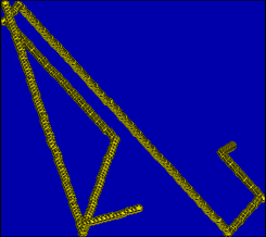
typical trace picture for the kin. gas theory: angles in the trajectory mark collisions.
3) Example to chaos theory: chaos1.mds, chaos2.mds
Aim: The example is meant to illustrate the probably most well-known
statement of the chaos theory, which is that the most minute changes may
produce fatal results. This statement is extremely important for the
simulation of physical processes (e.g. research on climate change, hurricane research).
The butterfly-example cited very often in this context (the flapping of the
wings of a butterfly may cause a hurricane in another part of the world) seems
to many people as a gross exaggeration. And though this has no negative
consequences for the average citizen, ignorance of the "fact chaos"
in the industry could cause losses in the range of millions, because even
the most simple algebraic terms like those of the quadratic
potential behave highly chaotic after
few iterations. If these effects are neglected in designing and evaluating
an industrial simulation program, misconstructions might be the result which
could possibly mean the ruin of a firm.
Set-up: For clarity reasons a simple two-dimensional set-up has
been chosen. Quadratic has been selected as potential.
The cutoff is set to 1m gesetzt, i.e. it is deactivated
since this is longer than the diagonal of the box (maximum distance of particles).
Thus the potential becomes physical nonsense, but you get very strong forces
this way.
The ensembles of the files "chaos1.mds" and "chaos2.mds"
are completely identical with the exception of the z-coordinate of the
particle marked red.
In "chaos2.mds it has been increased by 1 at the 18th digit (Remark:
MDS only displays the coordinates rounded to 17 digits).
This corresponds to a deviation of 0.0000000000000002 percent.
Execution and observations: (Remark for the teacher: If you show
this experiment in class, you could have the students make guesses about
how many steps it will take until the deviation shows.)
When the simulation is now started, the particles remain in a plane for
"chaos1.mds", but when you repeat the experiment with "chaos2.mds"
it only takes 230 steps till the first particles leave the plane.
For Lennard Jones potential it takes 2200 steps even though this
potential contains r in a much higher
power. This is easily explained because the quadratic potential produces very
extreme values if used without cutoff, while the
Lennard Jones potential produces values within a small interval, because it
approaches 0 as r increases unlike the quadratic potential which
approaches infinity. You can see that complicated functions do
not necessarily behave more chaotic than simple ones.


Ensemble after 2500 steps (Lennard Jones): left picture without error, right picture with error
Aim: The aim is to illustrate the planetary movements at a "handy" model and give evidence for the non-obvious fact that Kepler's Laws are fully included in Newton's gravitational law.
Set-up: The set-up consists of a central star and two planets
circling around it. The mass of the star is that of our sun, that of the
red planet is Earth's and the mass of the magenta-colored planet is the
same as that of Venus.
Since the trajectories of the planets in out solar system are to close to
circular, fictitious ellipse trajectories have
been chosen (nonetheless the names Earth and Venus will be used for
the planets in the following).
The proportions of the planet radii are the same as in reality but for
display reasons the radius of the sun was dimensioned smaller.
Execution and observations:
a) Kepler's first law states that the trajectories of the planets are
elliptical with the sun at one focus.
If you activate Display/Smiley windows/slime tracks
and let the simulation run for a while you can visually confirm that
statement.
For mathematical evidence you must first determine the maximum and minimum
x- and y-values of the two planets' trajectories.
Half of the difference ymax-ymin
equals then the length of the semi-minor axis b
(bEarth=1.03*1011m,
bVenus=5.65*1010m)
and from the x-values you get the length of the semi-major axis a
(aEarth=1.10*1011m,
aVenus=6.35*1010m).
From the smallest distance dk to the sun
you can calculate the linear eccentricity with the formula e=a-dk
(eEarth=3.89*1010m,
eVenus=2.92*1010m).
The results match the equation e2=a2-b2
very well (Deviation from e less than 1% both times).
b) According to Kepler's 2nd law, a line drawn from a planet to the sun
sweeps out equal areas in equal times.
This will be shown at the example of two areas. For doing this, imagine a
vertical line through the center of the sun. The part of the area of the
ellipse left of the line be F1
and the area to the right be F2.
With the data gathered above you can calculate F2=b/a*[a2*p/2-e*
sqrt(a2-e2)-a2*arcsin(e/a)]
and F1=abp-F2.
The results are: F2Earth=9.95*1021m2,
F2Venus=2.46*1021m2,
F1Earth=2.56*1022m2,
F2Venus=8.81*1021m2.
For determining the times in which the respective distance vector moves
across the areas, set the step counter to 0
(Experiment/reset step counter) the moment
the observed planet is at the boundary line between the two areas.
Then start the simulation and stop it after the planet has travelled around
the respective area. The results are tF1Earth=72000steps
and tF2Earth=28000steps,
and for Venus tF1Venus=34000steps
and tF2Venus=9700steps.
Both times the equation tF1/tF2=F1/F2
is true with acceptable precision.
c) Kepler's 3rd law says that squares of the periods of revolution of
the several planets about the sun are proportional to the cubes of the
semi-major axes of the ellipses.
To get the periods of revolution, you set the step counter to 0 and let the simulation
run until the observed planet has reached the starting point again after
10 rounds (for greater accuracy). Thus you measure as time for Earth
(TEarth=1.00*105steps)
and for Venus (TVenus=4.40*104steps).
The deviation of T2Earth/T2Venus
from a3Earth/a3Venus
is less than 1% which means that the law can be regarded as accurate.
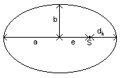 Die
Planetary trajectories are ellipses with the sun in one focus.
Die
Planetary trajectories are ellipses with the sun in one focus.
a semi-major axis
b semi-minor axis
dk minimum distance planet - sun
e linear eccentricity
S sun
All rights to the program Molecular Dynamics Simulator and the rights to this documentation are the property of Matthias Benkmann.
Please send feedback to Matthias Benkmann (m.s.b (a) gmx.net)